Air Bearings for High-Power Turbomachinery
In this technical paper, we will be discussing considerations and solutions for the use of oil-free turbomachinery operation as put forth in Enabling Bearing Technologies for High-Power Oil-Free Turbomachinery, by Bugra Ertas of the Mechanical Systems department at General Electric’s Research Center.
Ertas discusses the advancements in gas-film bearing technology and the work involved in pushing towards hydrodynamic bearings that operate off process fluids. The paper concludes with the potential for porous media air bearings to represent the next evolution in turbomachinery. And, we expand upon this point to demonstrate the qualifications of New Way® products for turbomachinery applications which necessitate high damping and maximally-loaded support bearings.
For power generation in the megawatt range, virtually any type of compressor or turbine utilizes oil-lubricated bearings. But, as demands for efficiency and power density increase, the industry is looking toward the use of bearings which lubricate and work off their machine’s own process fluid. While oil is capable of producing substantial hydrodynamic pressure and high damping through its naturally high viscosity, they’re held back by the need for complicated pump systems, as well as the need to protect the lubricant from process fluids—and visa versa—as noted by Ertas.
Ertas notes the two primary challenges involved in moving to gas/fluid bearings are their load capacity and ability for damping.
Loading
The most currently employed gas bearing is the foil bearing (shown below in figure 1.)— a hydrodynamic bearing which uses pressure generated between a compliant bearing “foil” and top surface to carry the shaft load.
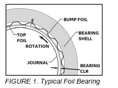 The foil bearing represents a strong foundation for the usage of gas bearings in turbomachinery, but it isn’t without its drawbacks, as shown by the torque-speed chart below in figure 2.
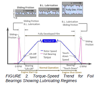
Figure 2. demonstrates the torque-speed chart for a foil bearing during its operational cycle. At 0 RPM we find a torque spike, as the foil and bearing surface are still contacting. After liftoff, the bearing produces a stable lubricating film at normal operation. But, this initial sliding friction and its associated torque spike still necessitate the use of surface coatings to resist sustained frictional contact.
This contact ultimately restricts application of the foil bearing to lighter rotors and, thus, lower power applications. Here we see the first hurdle already handicapping a technology, as the foil bearing’s contact friction on startup reduces its ultimate load capacity.
Damping
The second primary hurdle to the adoption of gas bearings is damping, which Ertas defines as the mechanical force which opposes vibratory velocity in a mechanical system. Functionally stated, damping reduces the frequency and amplitude of a system until it is at rest, making it a valuable tool in reducing harmful vibrations or potential resonance in a mechanical system.
Figure 3., shown below, represents a basic illustration of the relationship between vibration level and damping coefficient in a simple system, composed of an unbalanced rotating force acting as the forced vibration input. This simple example shows that as the damping coefficient is increased and stiffness held constant, the vibratory levels are reduced.
A similar example is demonstrated below in figure 4., however, this time the damping coefficient is held constant and stiffness is varied. Here, we see that lower stiffness results in a much quicker return to a stable, unperturbed state.
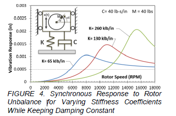
Ertas notes that the need for damping increases in a high stiffness case so as to retain the same amplification factor as a low stiffness case. And, thus, damping alone is insufficient in order to define the damping capability of a spring-damper system.
To fully realize the damping and stiffness capabilities, we must examine the ratio of stiffness-to-damping, which we define as the damping ratio (equation 1). The damping ratio relates to the critical damping (equation 2), wherein the system returns to equilibrium without any oscillations, to the absolute damping of the system.

With these equations defined, we see that to maximize our damping ratio, we must engineer a mechanical solution which allows for both low stiffness and maximum damping. While gas-film bearings normally exhibit a high stiffness ratio, newer hydrodynamic designs push back on this old wisdom.
Evolution of Gas-Bearing Systems
In this section, Ertas highlights the evolution of modern-gas bearing systems and how their individual design characteristics evolved to better accommodate higher-loading situations and provide for more damping.
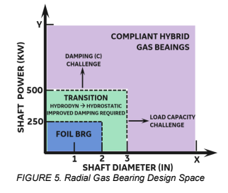
Figure 5. defines the basic parameters for the radial-gas bearing design space. Here a fundamental correlation is defined; that as power rating increases, so must the rotor diameter. And, therefore, weight grows larger to accommodate this power generating capability. This design space offers valuable insight into the applicability of existing and newly accepted gas-bearing solutions.
For example, we see that foil bearings are largely limited to smaller-diameter shafts operating below 250 KW, due to the collapse of their hydrodynamic film and the corresponding surface contact sustained by heavier shaft applications. Above the foil-bearing regime, hydrostatic pressurization comes into play.
Hydrostatics involves utilizing an external pressure source to lift the rotor, providing a higher level of fluid force to suspend the rotating assembly, which otherwise couldn’t be provided through a process gas-foil bearing.
Ertas notes that at higher power ratings, the fluid forces being used to support a rotating shaft also induces destabilizing dynamic forces (e.g. vibrations), which in turn necessitate higher levels of damping. This returns us to one of our initial hurdles to the adoption of compliant-gas bearing systems. And, Ertas identifies soft-bearing supports in conjunction with gas-film to provide adequate damping.
Compared to rigid geometry for hydrodynamic or hydrostatic systems, soft mounting on flexible supports provides a more favorable stiffness to damping ratio. And, thus, a superior damping capability. It may be noted that this system is already widely adopted in aircraft engines; the use of soft mounts turns rotor-bending moments into rigid-body moments. And, thus, reduces transmitted-bearing loadings and the magnitude of rotor vibrations.
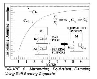 The above graph in figure 6. demonstrates how soft supports help maximize the equivalent damping of a spring-mass damper system. Defining Ka as gas-film stiffness and Kb as bearing-support stiffness; a simple relationship shows that as Ka/Kb approaches infinity, the equivalent damping approaches the bearing support damping. Phrased another way, reducing the bearing-support stiffness while holding gas-film stiffness constant, allows equivalent damping to rise.
Even when dealing with a relatively low-gas film damping value, this relationship allows for highly-damped systems by minimizing bearing-support stiffness (i.e. soft mounting).
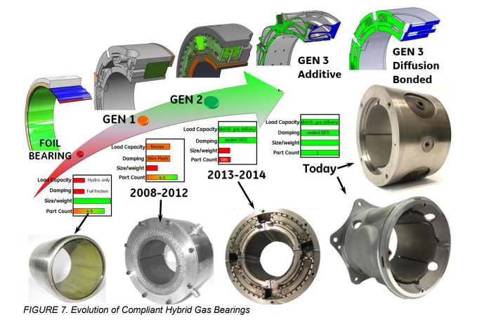
In figure 7, we see the progression and evolution of compliant-gas bearings over the past decade. Beginning with foil bearings, which offer an excellent size to weight ratio, we move into Gen1, which utilized a square cross-section for its hydrostatic recess to create a lubricating film layer between bearing surface and journal. This improved upon foil bearings by implementing a metal-mesh damper to load capacity and damping, but vibration mitigation was still limited.
Gen2 used a distributed-gas delivery system with multiple orifices to create its squeeze-film effect. And, while it offered higher damping, its 500-part assembly of modular-fluid dampers made manufacture and assembly impractical. Gen3 concepts offer the best of both worlds through additive manufacturing and provide a cost-effective solution. However, as noted by Ertas, the wear on the bearing-and-journal couple still remains.
Ertas closes his paper by explaining the remaining challenges facing gas-film bearings in turbomachinery applications. Namely, they must withstand unintended touchdown conditions. Furthermore, he highlights porous media air bearings as a potential solution for maximally loaded cases and suggests a combination of porous media air bearings coupled with a Gen3 compliant bearing.
The Case for Air Bearings in Turbomachinery
Now that we’ve covered Ertas’ thorough discussion on the adoption of gas-film bearings into the turbomachinery industry, we at New Way Air Bearings would like to expound upon his last point and discuss in-depth how porous media air bearings are uniquely suited to the maximally-loaded turbomachinery applications we’ve just discussed.
This discussion will pull heavily from our own internal testing, product specifications, and the work of our Chief Technology Officer, Drew Devitt, and his white paper, Damping and Stiffness, A Primer.
Loading
In the preceding paper, Ertas identified the limited loading capability of foil bearings as the primary obstacle to their widespread adoption for larger machines, as the bearing must withstand sliding friction and the touchdown weight on its flexible foil.
New Way’s bearing technology is fundamentally scalable and our radial air bearings, already in use for rotor balancing, and other high-speed rotary applications, allow for highly-loaded shaft applications.
An S32150L, 150mm x 300mm radial air bearing can support 2,350 lbs at an ideal 5-micrometer fly height and is capable of supporting shafts ranging from 250mm up to 1250mm in diameter. The highly modular nature allows for the application of multiple bearings in load-bearing positions, both axially and radially to support even heavier shaft applications
The nature of our porous carbon, integral to the creation of the air film, also tackles the issue of touchdown and sliding friction. Our porous carbon has a compression strength of 13,200 psi, or 91Mpa, making it relatively soft, allowing it to compress under loadings and unexpected touchdown, preventing vibration and damage.
Damping and Stiffness
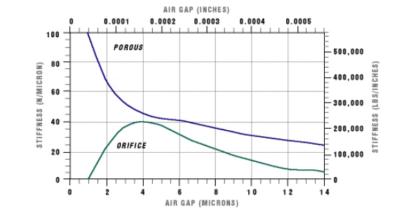
New Way’s Porous Media™ air bearings offer an ideal mixture of stiffness and damping via their application of the squeeze-film effect. While most mechanical systems find stiffness and damping inversely correlated, here, they’re positively related (as we see below in figure 7., taken from Technical Report One).
Because air bearings find the 5-micrometer fly height range as their optimal operating area, the air bearing already has an optimized stiffness-to-damping ratio. And, decreasing the air gap further increases the damping capability. If damping needs to be maintained while stiffness is reduced, the air bearing system can be soft mounted (per Ertas’ suggestion).
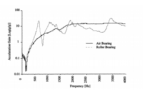
New Way’s air bearing products have already undergone independent testing to determine their damping capabilities against traditional-roller bearing systems, and this benefit holds true when compared to fluid-bearing technology as well.
Testing by Michael Chiu of MIT (covered in Technical Report Three) determined the frequency response of a linear air bearing over a 4000Hz frequency sweep, compared to an equivalent roller bearing system. The results, shown below, depict an almost perfectly smooth, asymptotic curve, free of the numerous poles produced by the roller bears, of which each pole is capable of producing resonant behavior.
Furthermore, Devitt notes that the spring rate of a fluid film or the force required to compress a spring (or a film acting as a spring) through a unit of distance is highly dependent on film thickness. And, for process gas-foil bearings, film thickness is a result of rotational speed.
If using an oil-based bearing, temperature will affect viscosity. And, it, in turn, affects the film thickness. This temperature spike is a result of heat generated by fluid shear, but because fluid shear is vastly lower in aerostatic bearings, New Way Air Bearings sidesteps both of these problems, supplying an external pressure to maintain film thickness and allowing for efficient thermal exhaustion through the air gap. This allows for externally pressurized bearings to maintain their stiffness and damping properties independent of speed or temperature, and resolving the issue of wear and tear on touchdown.
Ease of Manufacture
Ertas highlighted the Gen2 and Gen3 bearings as excellent innovations towards a widely applicable gas-film bearing only hamstrung by the complexity of their manufacture. The Gen2 bearing had 500 individual components, while the Gen3 bearing required additive manufacturing, and still suffered from wear between the bearing and journal.
New Way bearings are not just easily and consistently manufactured, they’re designed and machined in house, and virtually every product we offer can be scaled up and manufactured to your exact specifications.
Contact Us
Across all relevant metrics, be it loading, damping, stiffness, or ease of manufacture, externally pressurized Porous Media is situated to make gas-film bearings a mainstay for turbomachinery. If you want to speak with us regarding a turbomachinery application, please contact us so we can discuss what New Way Air Bearings can do for you!
Learn More About the Porous Media Difference

