The Application of Damped Air Bearings For Machine Tools
In this technical paper, we examine the application of air bearings and Porous Media Technology™ to metal cutting and machining applications. Results comparing the straightness, stiffness, and dynamic response of air bearings to rolling elements are discussed, as well as ideal mounting configurations, products, and proven test cases.
The Problem of Machine Motion
Machine tools have always required a means of motion and have long aimed to reduce friction, and increase mechanical efficiency. The earliest machine tools relied on plain bearings. The transition from plain bearings to rolling element bearings brought with it an order of magnitude reduction in friction, from a friction coefficient of 1 down to 0.001. Additionally, rolling elements enabled higher speeds and greatly reduced backlash, creating the first major leap in precision engineering.
Now, the transition begins from slide ways to linear guides, and into the future with systems built on fluid film bearings. Fluid film bearings offer a substantial benefit over virtually all other bearing technology. When motion occurs on a fluid layer, like air, wear and friction are eliminated and accuracy is improved, since surface imperfections get averaged out over the film gradient.
The Solution of Porous Carbon
Porous Carbon Media, the foundation for all of our New Way® products offers a plethora of advantages and distinguishes itself as the next evolution of fluid film bearings. For machining applications, stiffness, stability, and damping are all paramount, and each is intertwined with the other. Dynamic stiffness (explained in detail here by our partners at Bently Bearings) is defined as the ratio of a force to its observed vibration, or response.

Vibration resistance is an important trait for any precision machining setup, and is essential for surface finishing application, tool lifespan, and the reduction of subsurface damage when grinding ceramics. Furthermore, high-dynamic stiffness is essential for controls to function properly on high-performance machine tools.
While damping itself is a dimensionless quantity, it describes how a system oscillates in response to a disturbance. Broadly speaking, overdamped damped systems are more preferable than underdamped systems, as underdamping can lead to resonant behavior and a system which never returns to equilibrium if perturbed.
Traditionally, air bearings (which for the longest time were purely orifice bearings) were considered to be technology with low stiffness, low stability and a low damping function— primarily a result of the bearing’s instability under loading and the orifice bearing’s vulnerability to the “pneumatic hammer” effect (see the stability and porous compensation section).
With the advent of Porous Media™ and New Way’s in house testing, we’ve demonstrated that air bearings exhibit the opposite behavior from their orifice bearing brethren.

Figure One: Orifice vs Porous Media Stiffness Curves
In figure one, shown above, we compared the stiffness curves for a porous media bearing vs a traditional orifice bearing. Due to the uneven pressure distribution and tendency for collapse (when the region is starved for flow and pressure), orifice bearings lose stiffness under a decreased air gap, dropping off to zero and collapsing.
By contrast, a smaller air gap actually increases stiffness for porous media, largely owing to the squeeze film effect. This positive correlation between stiffness and damping is virtually unheard of in machine design, and makes them uniquely suited to machining applications.
Testing the Limits of Porous Carbon
While we are proud to conduct our own in house testing at New Way, we’re just as proud to support our colleagues in industry and academia as they explore the full potential for porous media air bearings. The following tests and results are derived from the paper Low-Cost, Highly Damped, Precision Linear Motion, Using Porous Carbon Air Bearings and Epoxy Replication by Michael Chiu of MIT, in coordination with Drew Devitt of New Way and Bradley Damzo at the National Institute of Standards and Technology.
The aim of Chiu’s research was to develop and design a manufacturing method for high-precision linear bearing systems, and to then test those systems against ones based on conventional-rolling elements.
Test Setup
Chiu acknowledged that the first step towards building a better system for precision motion began with its mounting system. Both match grinding and swiveling, while available, are often not ideal for long, linear applications. Thus, a brand new technique called vacuum replication was pursued.
The vacuum replication process (patent protected) involves plumbing individual air bearings to vacuum against the guide surface. With the bearing now vacuum-fixed to the guide, the bearing housing is positioned overtop of the bearing, leaving a small gap between housing and bearing.
A replicant (epoxy) is then injected into this gap and allowed to cure under continued vacuum. After the curing process is complete, the entire assembly is now accurately fixed to the guide surface. The pressure from the air bearings generates a fluid film thin enough for running motion, while the cured epoxy bond eliminates the stiffness and instability found in flexural and ball-socket designs (see page 41).
The completed test setup, as shown below in figure two, demonstrates the relationship between the bearing guideway, bearing surface, and epoxy fixed carriages.
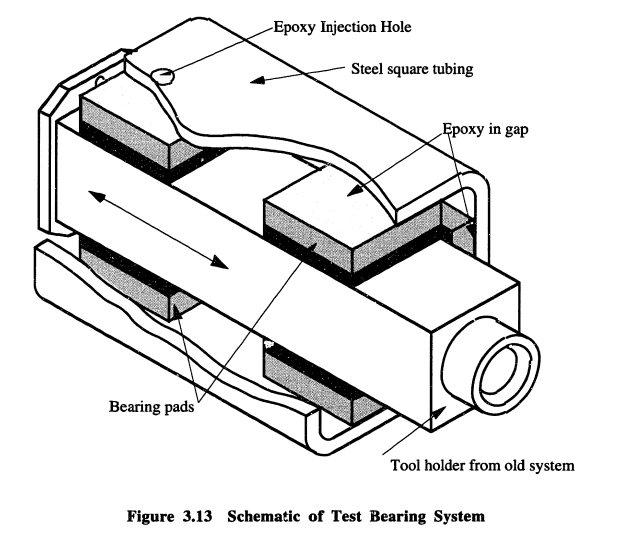
Figure Two: Test Setup
Static Stiffness Testing
For static stiffness, a test setup was developed wherein a pneumatic cylinder was used to apply a known ,variable load, measured by a capacitance probe. These tests were performed on the bed of a knee mill, with the cylinder mounted in the spindle chuck and the tool carriage supported by air bearing pads, as shown below in figure three.
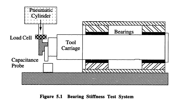
Figure Three: Static Stiffness Test Setup
Chiu showed that the behavior of an air bearing and its associated structural properties may, like many phenomena be modelled via the analogy of a voltage divider electrical current, wherein voltage is analogous to pressure, current to flow and resistance with decreasing gap (page 24). Thus, the stiffness is measured as resistors in series, shown below in figure four.

Figure Four: Static Stiffness Circuit Analogue
The results for stiffness were calculated by taking the derivative of the force-displacement curve and is shown below in figure five.
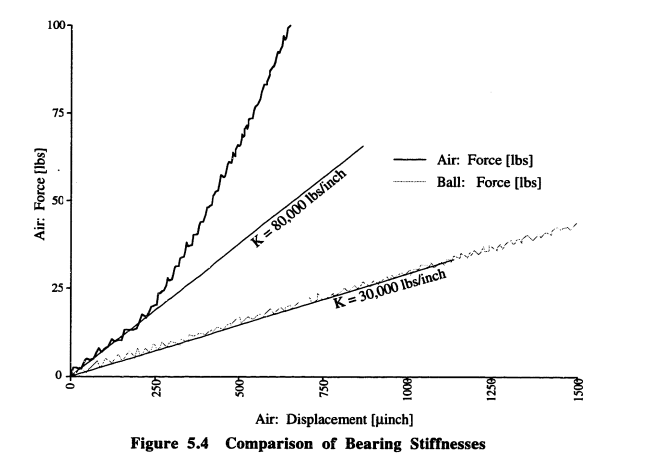
Figure Five: Air Bearing vs Ball Bearing Stiffness Curves
As we see in the curves above, the ball bearing produces a linear stiffness, leading to an approximate K-value of 30,000 lb/inch, while the air bearing exhibits a non-linear, almost exponential response, with a true K-value approaching 160,000 lb/inch, creating a system five times stiffer than the existing, contact design.
In addition,Chiu notes the presence of a large hysteresis curve when loading and unloading the roller bearing system (page 67), introducing the potential for significant error when cutting against the bearing.
Straightness Testing
For straightness testing, the configuration shown below in figure six was utilized. A potentiometer with constant voltage source was used to measure axial position, while a capacitance probe measured lateral displacement.
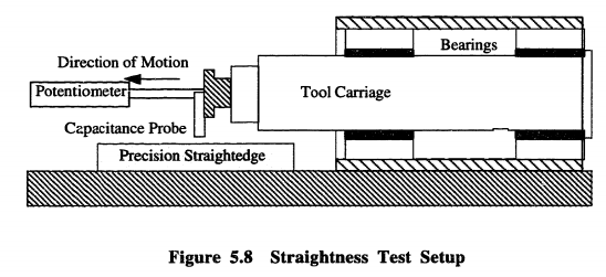
Figure Six: Straightness Testing Setup
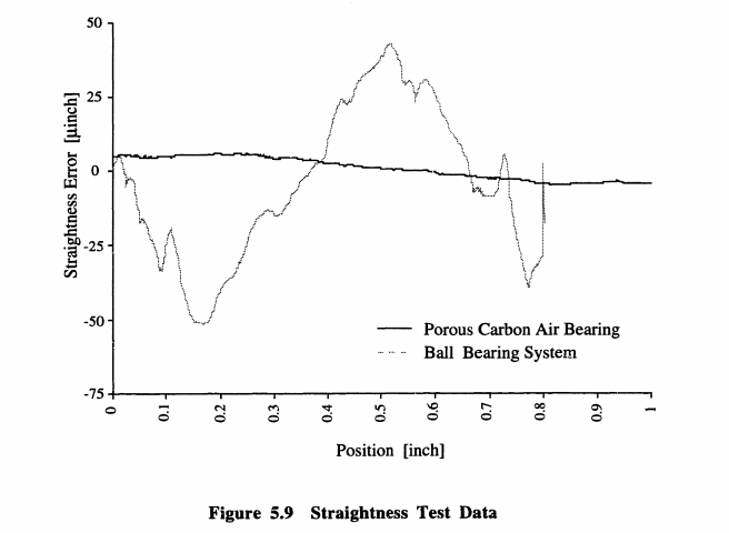
Figure Seven: Straightness Test Data
The results, shown above in figure seven, demonstrate straightness data for a porous carbon air bearing vs. a roller bearing system. Over a length of one inch, the air bearing produced approximately 10 micro inches of error motion, while the ball bearing system produced a peak-to-valley error almost 10 times that, varying from -50 up to 50, with numerous peaks likely caused by material imperfection.
Aside from producing far less error motion overall, the air bearing systems also generate a smoother curve allowing for more consistent behavior and predictable motion, ultimately allowing for the production of precisely machined components.
Chiu also conducted a larger-scale test for the air bearing system over a distance of 12 inches, the results of which are shown below in figure eight. The original bearing surface produced an average straightness of 20 microinches per inch and a peak-to-valley error of 150 microinches.
Due to the effects of air-film averaging afforded by air bearing technology, we saw an average straightness of 70 microinches per inch, a three-times improvement in operating straightness
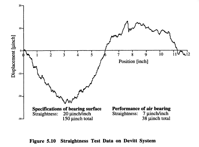
Figure Eight: Air Bearing Straightness
Dynamic Response Testing
For dynamic response testing, a drive point impulse method was utilized, with an accelerometer mounted to a point which corresponds to where a tool would be mounted. A calibrated impulse hammer was used to apply a known impulse, and the results (shown below in figures nine and ten) were collected with a signal analyzer.
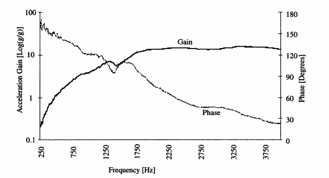
Figure Nine: Air Bearing Dynamic Response
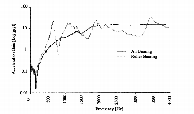
Figure Ten: Air Bearing vs. Roller Bearing Dynamic Response
As evidenced by figure nine, we see that the air bearing system produces an extremely smooth gain between 250 and 3750 Hz. While the phase curve exhibits the possibility of resonance in the 1250-1750 area, the smoothness of the curve and the flat peaks speak to an extremely well-damped system with little risk of resonant behavior.
Contrast this with the roller bearing results in figure ten, and we see just how poorly damped a contact motion system truly is. The roller bearing system produces numerous sharp, narrow peaks, and each of these is capable of causing resonance if properly excited.
From Theory to Practice
New Way is immensely grateful for the work of Chiu into proving air bearings as the superior platform for precision machining. For us, however, theory is not enough. At New Way, we believe in leading by example, which is why we already utilize air bearing products for our in-house machining capabilities and in the production of our air bearing product line.
Dry Diamond Machining
While this was once a theoretical application, New Way has used a combination of Radial Air Bearings and Flat Round Air Bearings to construct a Dry Diamond Turning Machine capable of handling pieces three meters in diameter. The radial air bearings allow rotation of the table and support radial loads from the milling tool, while the flat round air bearings at the table’s edge support axial loads from the weight of the workpiece. Without friction, the workpiece can spin smoothly, resulting in a more precise fit and a smoother finish.
Floating Micrometer
Frictionless Motion®️ also allows for us to inspect and validate our products to a high degree of fidelity. Here we’ve developed a floating micrometer which uses three flat rectangular air bearings to flat a Starrett Micrometer on a granite workbench. Because the air bearings never contact the workbench, any surface deviations are averaged out, and the only friction an inspecting technician will feel is from the contact of the tool against the item being measured.
Air Turn Production
We also use air bearings in the direct production of our own air bearings, like this set up for machining air turns. Here, the shaft and drive motor are supported by radial air bearings, providing axial and redial constraints to the assembly. The grind wheel itself is mounted on an air spindle assembly while the grind wheel assembly as a whole is mounted to a rectangular air bearing, allowing for it to translate along the grant workbench with functionally infinite resolution.
Contact Us
Having seen the math and how we use our own air bearings, if you want to reach out to us to discuss how New Way Air Bearings can further improve your machining process, or if you just want to ask a question, please contact us!
Learn More About the Porous Media Difference

