A Precision Air Bearing Stage, Containing A Moving Vacuum Chamber
There are a number of different fields which require increased precision in vacuum environments. Mask making and repairing, direct e-beam patterning of wafers and CD-SEM are examples where higher precision is required in vacuum for manufacturing next-generation integrated circuits. Although air bearings have been successful in many high-precision patterning and inspecting applications, they present obvious problems in the deep vacuum environments required by shorter wavelengths.
So, conventional precision systems in vacuum often employ stacked rolling element stages that are built up from the floor of the vacuum chamber or hang from the top of the chamber. This creates relatively long structural loops with low natural frequencies, and necessitates large vacuum chambers with long pump-down times. Also, this paradigm requires that the diverse service components of the stages be inside the vacuum chamber, creating additional surface areas which may out gas or retain moisture.
Methods to keep the mechanization outside of the vacuum chamber have also been employed previously. These include linear and rotary contact seals, rotary Ferro fluidic seals, and expanding and contracting bellows. Air bearing structures have also been utilized where they are separated from the vacuum chamber by integral differentially-pumped grooves that support some sort of a moving member through an aperture in the vacuum chamber wall. The difficulty in these solutions is in maintaining the structural integrity to satisfy the precision required by new applications.
The Concept
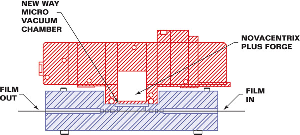
Instead of trying to build a stage inside a vacuum chamber, or reaching through a chamber wall, the concept under test provides for the stage itself to become the vacuum chamber. Having the only (or primary) vacuum chamber completely contained inside the moving stage means that all motion systems can exist outside of the vacuum. Guidance of the stage in the plane established by the X and Y-axis is achieved with an annular air bearing separated from the vacuum section of the stage by differentially pumped grooves. The air bearing surface bears directly on the reference plate to which the energy source is attached, dramatically shortening and stiffening the structural loop. Because the vacuum chamber size is reduced to little more than the volume of the substrate, vacuum pumping requirements and pump-down times are dramatically reduced and the requirement for a large conventional vacuum chamber is avoided.
The work reported in this paper summarizes the relationship between air bearing gaps and the sealing effectiveness of the differential grooves by empirical testing. Since air bearing gaps also have an important effect on the static stiffness and damping properties of the suspended stage, these factors are also documented and related to vacuum performance. Static stiffness is determined by load and displacement measurements, and dynamic properties are investigated using accelerometers and a signal analyzer.


![]()
Figure 2
Set UpFIGURE 2 shows the porous air bearing land, sealing lands and pumped grooves. Behind, the counter surface of the base is visible. Both are faced on a diamond turning lathe.

![]()
Figure 3
FIGURE 3 Once together, one probe mount and target are seen in the foreground bolted directly to the base and stage respectively. The targets on the stage were faced with the lands. The rubber bands constrain the stage in X and Y without influencing Z.
Pressures, Flow and Lift
A pump capable of maintaining 20 inches of Hg at 80 CFH was used to pump on the first groove. A rotary vane pump capable of 10-3 Torr was used to pump the second groove. The third groove and the chamber were pumped by a turbo pump, using another rotary pump to back it up. A valve allowed for pumping on both the chamber and the third groove or, when closed, just the chamber itself. Pumping independently on the third groove with another pump will significantly improve the vacuum levels. It is notable that we were able to pump the chamber to 10-6 Torr in 10-to-15 minutes. We attribute this to the small volume of the chamber. It is 210mm in diameter (sized for 200mm wafers) and only 262cc.

Dynamic Behavior
Background vibrations were checked and found to be on the order of 25nm. This was the same whether the air pressures to the bearing face were on or not. The air bearing’s air film did not adversely effect the stiffness of the structure. This is consistent with previous dynamic studies indicating that there is very high damping (15 to 20%) of modes up to 700Hz. Higher modes of 1500Hz and up were dominated by bending of the bearing housing and showed much lower damping (2%). The best compromise between stiffness and damping seemed to be between 10 and 15 microns. Although stiffness increases with smaller gaps, the damping is reduced.

![]()
Figure 4
FIGURE 4. A data stream from a capacitance probe when struck with a hammer while the air pressure was off (bearing grounded) and full vacuum on.

![]()
Figure 5
FIGURE 5. A data stream from a capacitance probe when struck with a hammer while the air pressure was on (bearing flying at 120 micro inches) and full vacuum on.
Static Stiffness
The vacuum preloading force on this bearing is about 1700 pounds. By allowing the first groove to flood with atmospheric air pressure, the load on the bearing is reduced by 150 pounds, and the measured change in the fly height seen in Figure 6 is 11.8 micro inches. This results in about 12.5 million pounds-per-inch in axial stiffness at a fly height of 150 micro inches.

![]()
Figure 6
FIGURE 6. It is interesting to note that changes in input pressure resulted in very fine, accurate and stable displacements.
Future Work
We believe that the Vacuum Chamber Stage described here could see rapid adoption among EUV Source and Resist Suppliers as this technology could dramatically reduce the cost of their research equipment.
1. Marsh, Eric Machine Dynamics Lab, Penn State, University Park, Pa. for help with the dynamic work.


