New Way Air Bearings® always strives to test our air bearings products to the best of our ability. And, we’re just as happy to support our industry partners as they study and evaluate the applicability of our products to new industries and applications.
This technical report covers the paper Experimental Assessment of Drag and Rotordynamic Response For a Porous Type Gas Bearing, written by Luis San Andres, Sung Hwa Jeung, and Drew Devitt, as submitted to the Society of Tribologists and Lubrication Engineers (STLE) 2015 Conference. This paper contextualizes air bearings as an ideal solution for supporting lightweight rotating equipment while removing cumbersome lubrication equipment from the equation.
The primary benefits to air bearings for rotary applications, as we discussed in Technical Report Six, and further confirmed by the authors of this paper, lie in the high stiffness and damping coefficients available to air bearing based support, and which enable precise control of rotor displacement induced by dynamic forces.
Test Rig Setup
This test focused on understanding the physical implementation of air bearings into high-speed rotor systems, and to assist with building a knowledge base regarding the usage of non-contact supports for rotating equipment. In order to conduct this test, two identical air bearings supported a rigid rotor-motor, fixed by a stiff armature.
Two end caps with flexible thrust pins controlled the rotor’s axial displacement. And, the rotor was spun up the 55 krpm via a three-phase motor. Rotor displacement was measured via the use of two pairs of eddy current sensors positioned orthogonally in the support structure, and facing the rotor ends. These boots were displayed through oscilloscopes while a high-speed, infrared tachymeter measured the shaft speed as well as providing a keyphasor signal. This test setup is displayed below in figure 1.

Figure 1:Test Rig Setup
The rotor itself was supported by a trio of conformed air bearing pads, similar to our Radial Air Bearings, and mounted on ball pivots to allow for adjustment and radial preload. As is standard with all New Way products, the air supply contained a flow valve, air filter, pressure regulator, and flow meter to monitor and regulate the air supply into the bearings. Figure 2 below, demonstrates the tilting pad air bearing support system.

Figure 2: Air Bearing Support Configuration
Coast Down Speed Tests and Determination of Drag Coefficient
The first major test conducted using this experimental setup was to determine the drag coefficient of a rotor moving against an air bearing. As air bearings are a non-contact source of motion, understanding their precise drag coefficient is critical to calculating mechanical and energy efficiency gains which can be obtained by switching to a Porous Media™ based system.
The high-frequency driver powered the motor, spinning it to a maximum radial velocity of 55 krpm, or 82 m/s at the surface of the rotor. Next, the converter was turned off, and the rotor allowed it to coast down to rest from its maximum speed.
The governing equation for rotor angular velocity is shown below:
![]()
Here, the primary points of interest are setting IP as the rotor polar mass moment of inertia. We assume the drag torque accounts for the shear drag torque from both bearings as well as the torque from rotor windage losses (Twindage).
For the drag due to windage, we evaluate it as such:
![]()
And, write the coefficient of windage losses as:
![]()
What is most worth noting here is that our coefficient of drag is a function of the rotational Reynold’s number, and at a rotation velocity of 55 krpm, Re=5400, placing us well into the turbulent flow regime.
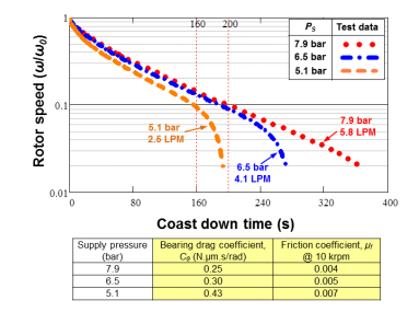
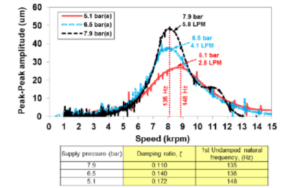
Figures 3 and 4 below show the results of this test. Figure 3 is a graph of coast-down time vs. speed, for three distinct values of Psi, while in Figure 4 we have speed vs. peak amplitude, similarly for differing pressure values.

Figure 3: Coast Down Time vs. Rotor Speed

Figure 4: Peak-to-Peak Amplitude vs. Speed
Figure 3 demonstrates coast-down times with the y-axis on a logarithmic scale, also displaying that the speed fraction decays linearly above 0.1. This shows up as the decrease in rotor speed is of the exponential variety, and expected for a system dominated by viscous, fluid forces. Furthermore, it reveals the simple, yet powerful fact that a higher supply pressure will keep the rotor spinning longer.
Figure 4 shows us a test that serves to assess the behavior of the system as it crosses the first, rigid body, critical speed. This response is due to the inherent unbalance of the rotor system, and what our test demonstrates is that changing the air supply pressure has a dramatic effect on amplitude and the system damping ratio.
Altering the air supply between 7.9 and 5.1 bar allows us to effectively modulate the system, dropping the peak amplitude from 50 down to 25 micrometers. Additionally, the table below figure 4 tabulates these results, and shows a marked reduction in the damping ratio, from 16% down to 10.6%. Furthermore, as the supply pressure increased from 5.1 to 7.9 bar, this also affected the system’s undamped natural frequency, bringing it from 170 Hz down to 151. This is highly significant since prior work in the field of hydrostatic gas bearings demonstrated natural frequency is positively, and not negatively, correlated with bearing stiffness and supply pressure.
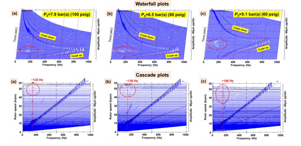
Figure 5 below, shows waterfall and cascade plots for the amplitude of rotor motion during ramp-up to, and coast down from, 55 krpm.

Figure 5: Waterfall and Cascade plots of amplitude during ramp up and coast down
Waterfall plots are a style of three-dimensional plot. For the waterfall plots on top, the x-axis is frequency, the y-axis is time, and the z-axis is amplitude of displacement. For the cascade plots, the x is still frequency, y is rotor speed and z is amplitude of displacement. The circled regions on the waterfall and cascade plots enclose an area of subsynchronous whirl motion, which varies with speed and amplitude, though confined to the first natural frequency.
Just as consequently as the results obtained from figures 3 and 4, these figures show that the whirl frequency ratio decreases with a decrease in supply pressure. Accordingly, as supply pressure drops, subsynchronous whirl motion occurs at a lower shaft speed and with a higher amplitude
Putting the Pieces Together
This test proved several fundamental relationships and characteristics of air bearings when used to support a rotating shaft. Measurements showed the air bearings formed a well-behaved system with largely synchronous motion, operating with viscous drag; indicative of an established thin-film layer correlated with bearing pressurization. Additionally, the test showed that a higher supply pressure decreases drag and allows for an extended period of near-frictionless operation. Increasing supply pressure also led to a reduction in damping ratio at the critical speed and while subsynchronous whirl motion is observed to grow above the first critical speed, the amplitudes are low enough so as to make them benign, and not indicative of rotordynamic instability.
Implications and Applications
While this report covers a very basic scenario, the fundamentals it establishes validate our view of a future turbomachinery industry built on air bearings. Due to porous media’s uniquely positive correlation between stiffness and damping, and as shown in the tests above, porous media has an unparalleled ability to damp resonant behavior and increase whirl speed, reducing fatigue on a system and extending its operational lifespan.
For more information on air bearings and their applicability to turbomachinery, we would encourage you to read Technical Report Six: Air Bearings for High-Power TurboMachinery as well as explore bentleybearings.com, where we continue our mission to honor the legacy of Don Bentley.


