When Guidance Dynamics Corporation needed to develop a friction-free testbed solution to accurately simulate robotic spacecraft, they turned to New Way. We paired them up with our Flat Round Air Bearings, providing an ideal foundation for creating a frictionless float uit over top of an epoxy testbed.
In coordination with Precision Epoxy Products, a division of Rock Art, Ltd, the article below details the use of New Way flat round air bearings in an Aerospace Test bed designed to support robotic spacecraft simulation.
Additional videos are provided showing these air bearings in use simulating docking and avoidance strategies for spacecraft. Special thanks to MIT Space Systems Labs and John Hopkins University Autonomous Systems Control Optimization Lab for producing these videos!
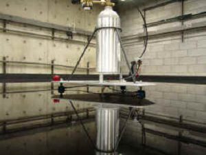
Douglasville, GA, January 24, 2014 — The consistency and accuracy required over a large area makes the time and tools needed to measure one of our Aerospace Epoxy Test Beds very expensive. In reality however, no matter how the surface is measured, what really matters is how your Robotic Spacecraft Simulator floats on the epoxy floor. An ideal test bed surface provides for little to no drifting of the float unit at any location on the test bed surface. If the float unit sits perfectly still when it is floating above a flat surface on a cushion of air in a state of weightlessness, then there is no doubt that the surface is perfectly level.
 The sophisticated Robotic Spacecraft Simulators being deigned and used on our epoxy test beds can detect when the unit is drifting and activate air thrusters to correct movement and stabilize the unit. This however is not a desirable scenario; the more the unit has to correct itself because of an imperfect test bed surface, the faster the self contained air supply of the unit is depleted which in turn reduces the duration of test time. The test bed surface not only needs to be level, it also needs to be smooth and nonporous. To further reduce air consumption, the test bed should allow the float unit to function with a minimal air gap between the test bed surface and the air bearing itself. This equates to a reduced flow of air through the air bearings resulting in a longer test time.
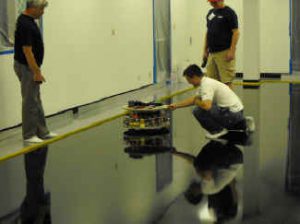
The evolution of Floating Robotic Spacecraft experimentation has come along way in a relatively short period of time. As you can see from the simulators pictured, no two are built the same. There are however common parallels that should be considered and incorporated into the construction of any Robotic Spacecraft Simulator. Before the availability of the Epoxy Test Bed from Precision Epoxy, any excessive drifting, turning of the float unit or the spinning of the unit during straight path movements and other irregularities during flight simulation was easily explained by potential flaws with the test bed surface.
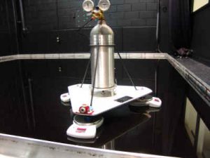
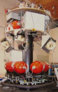
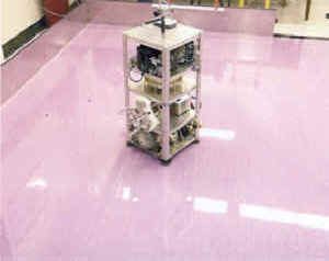 With the introduction of our test bed surface, indications are that some of these problems with flight simulation are caused by design flaws in the float units themselves. Corrections in design of your float unit will eliminate having to deal with such problems that distract from the time and resources being spent on the actual research being pursued. We addressed the three most obvious design flaws with the robotic float units we have seen and designed our own unit to function with consistency and dependability every time. Granted our float unit is as basic as can be and does not have a computer, GPS acquisition, thrusters, gyroscopes, reaction wheel, cameras or any of the hardware used on a Robotic Spacecraft using one of our Epoxy Test Beds. Our float unit is however, the first stage or carriage vehicle of any design that will carry additional accessories. No matter what the final vehicle ends up becoming or weather the design uses 3 air bearings at 120 degree intervals or 4 air bearings at all 4 corners of a square unit, the following three design principles need to be employed for the float unit to function with consistency and dependability. Pictured is a first generation Spacecraft Simulator on our Epoxy Test Bed at the Naval Postgraduate School’s Spacecraft Robotics Lab in Monterey, California.
 1) The first design consideration is the balance of the float unit. The total weight of the unit should be balanced so that it is distributed evenly to all the air bearings. Our float unit was constructed with careful placement of each component. Each component was machined to be of identical size and weight to anymatching component. In addition the size, weight and placement of each individual component were considered for proper balance. After construction was completed, the unit was scaled.
 Scaling is a procedure used in the Motorsports Industry as apart of set-up to prepare a race vehicle for racing at a particular race track. The vehicle is rolled onto a perfectly level surface called a Set-up Surface Plate. Then four identical electronic scales are placed under each of the four tires. The total weight of all four scales equals the total weight of the vehicle. The weight distribution from front to rear, left to right and cross weight (front corner to opposite rear corner) percentages can also be determined and adjusted.
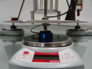
 The idea is to distribute the weight of the vehicle to all four corners (to each of the four tires) in such a manner to achieve a perfect balance that suits a race track’s characteristics; this allows for optimal handling and maximum speed. A float unit simulator is floating on a perfect surface and in order for it to track in a true direction, the unit needs to be balanced. To accomplish a perfect balance we placed our float unit on the perfectly level Epoxy Test Bed with each air bearing resting on one of three identical scales. At this point the balance of the float unit can be determined and counter weight added as needed so that one third of the total weight of the unit is supported by each of the three air bearings. It will be very hard to build a float unit that is exactly balanced without the use of counter weight. With proper planning and placement of components, the counter weight needed can be minimal. The float unit will need to be scaled every time a component is changed or added. Simply by changing the regulator valve on the air tank of our float unit from the one used in the original design to a smaller regulator, the balance of the unit was changed. Although the location used to place the counter weight remained the same, it required an increase from 82 grams to 136 grams. The overall weight of the unit remained the same. Equal weight distribution to each air bearing assures that the unit will have a true float path every time.
 2) The second design consideration is to assure an equal flow of air to each of the air bearings. When it was noticed that some of the the Spacecraft Simulator Float Units we saw tested had the air bearings plumbed in line from the air source to bearing number one, to bearing number two and then to bearing number 3 it immediately raised a red flag. The numerous negative scenarios possible with this type of plumbing system made it obvious that an uneven flow of air through each of the three air bearings could be encountered. Not having the identical flow of air through each bearing means that the air gap between the bearings and the test bed surface will not be the same. This will alter the weight distribution and throw the unit out of balance diminishing the possibility of a true flight path. Furthermore, should air flow be reduced through one bearing, the air gap could be reduced enough to cause that bearing to drag or hook the test bed surface. The only correction for this is to increase the pounds per square inch of air flow through the entire system resulting in decreased test time. By proper design of the air line plumbing system, negative scenarios can be reduced or eliminated and valuable time saved by not having to deal with the potential problems that will present themselves with a poorly designed plumbing system.
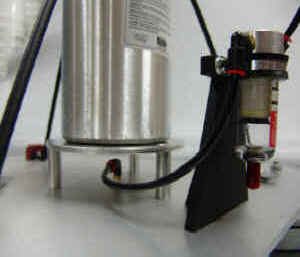
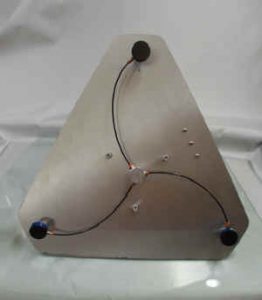 The design of the plumbing system for our float unit consist of a single air line from the air tank regulator to the filter staging area. Another single line runs from the filter out connection to a custom designed air manifold located in the center of the float unit’s 3/16 inch aircraft aluminum base plate platform and at an equal distance from each of the three bearings. Each air line from the manifold to each air bearing is identical in size and length. This design, unlike the in-line plumbing design, assures an equal flow of air to each air bearing. This air line design also allows for easy and positive isolation of any problems that can occur to the particular air bearing at fault. A clogged or dirty air bearing, an air leak from a cracked or damaged line or fitting and so on can be quickly located and corrected. Pictured is the under side of our float unit showing air manifold and plumbing to bearings.
The first stage or carriage platform of our basic float unit is now ready to have additional stages added as needed to accommodate additional hardware. Stages can be added at any size, shape or height required as long as they are positioned with the additional weight being balanced properly. We are currently using 40 mm bearings supplied by New Way Air Bearings in Aston, PA. The 40 mm bearing is rated by the manufacturer to handle a weight of up to 50 lbs at 60 psi. With a three air bearing carriage system, our unit should float up to 150 lbs dead weight. Our unit is currently at 26.5 lbs total weight which allows for additional add-ons of 123.5 lbs if needed with the existing air bearings. New Way offers air bearings up to 200 mm as well as all the mounting hardware.
3) The third design consideration is the choice of air to be used in the float unit’s compressed air storage tank. Normal compressed air will need an extensive filtering system to remove moisture, oil residue and any other contaminants that may clog or damage the air bearings. This can be a major problem causing unwanted down time.
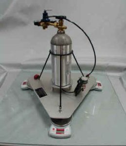
We decided on CO 2 for our unit because of its purity which in turn allows for a minimal inline filtration system. The likelihood of the air bearings being clogged reducing the air flow is also reduced. There is a wide selection of CO 2 tank designs and sizes available that can be found in various industries from the Paint Ball market to the Beverage Industry. These tank choices give more flexibility with the float unit’s design. Easy availability to have our tanks refilled was also a consideration.
This paper was posted to share the information we have learned through our experience over the years. We have designed and installed many perfectly flat and level floor plate surfaces of all sizes and for all types of uses giving us the insight for the suggestions contained herein. Furthermore, because our surfaces over large areas are so perfect, that to measure them for accuracy by any other means than the float unit validation, is neither a practical nor reliable method.
We would like to thank New Way Air Bearings for all their assistance and
for the outstanding products they provided for our Float Unit project.
Contact information:
New Way Air Bearings
50 McDonald Blvd.
Aston, PA 19014
Phone: 610-494-6700
Fax: 610-494-0911
Web: www.newwayairbearings.com
 A source for custom built turn-key Robotic Spacecraft Simulators or custom components is Guidance Dynamics Corporation. We have worked on several projects with Eric Rasmussen, President of Guidance Dynamics and his staff and have witnessed his units ranging from 3 degree-of-freedom to 6 degree-of-freedom in operation.
The Products they provide are very impressive. For more information visit their web-site at www.guidancedynamics.com .
Contact information:
Eric Rasmussen
Guidance Dynamics Corporation
4685 East Industrial Street
Suite 3A
Simi Valley, CA 93063
Phone: 805-582-0567
Email: rerasmussen@earthlink.net
Web: www.guidancedynamics.com
Similar Satellite Research Integrating New Way Air Bearings:
Learn More About the Porous Media Difference